








back to : hydraulic directional control valves
How to connect a hydraulic directional control valve?
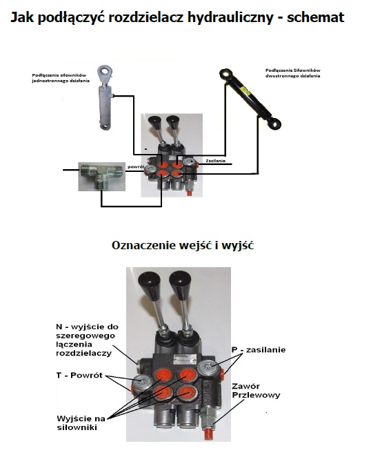
Connecting a hydraulic control valve requires knowledge of markings and the oil flow diagram. Thanks to the use of appropriate high-pressure carry-over plugs, it is possible to easily connect sections, allowing for the expansion of the hydraulic system's capabilities and its adaptation to more demanding applications. Click here on the tab HYDRAULIC DIRECTIONAL CONTROL VALVES to check the offer of hydraulic control valves. Our offer includes, among others, valves, parts for valves, nipples for valves, and hydraulic hoses for connecting actuators.
Click here to download the guide on connecting control valves
- P = supply
- T = return
- N = outlet for series connection of the valve
How to connect a hydraulic directional control valve ?
Connecting a hydraulic control valve is a key stage in the installation of a hydraulic system and requires precision and knowledge of the markings on the device. Hydraulic control valves manage the oil flow in the system, allowing control over the operation of actuators and hydraulic motors. Steps for connecting a hydraulic control valve: 1) Checking port markings – Each valve has markings for inlets and outlets that must be correctly connected: P (Pressure) – supply port, to which the supply line from the hydraulic pump is connected. T (Tank/Return) – return port, discharging oil to the tank. A and B – working ports, to which receivers are connected, e.g., cylinders or hydraulic motors. N (Neutral, BYPASS) – in some models, used for bypassing the oil flow. 2) Installation of hydraulic hoses – It is important to use hoses with the appropriate diameter and resistance to working pressure to ensure safety and performance efficiency. 3) Use of safety valves – In some installations, it is recommended to install relief valves to protect the system from overload. 4) Testing operational correctness – After connecting the valve, check the correctness of the oil flow and the system's response to control.
Markings on hydraulic directional control valves
Markings used in hydraulic directional control valves help in proper assembly and system configuration. The most common markings include:
- P – Pressure inlet (Pressure)
- T – Return to tank (Tank)
- A, B – Receivers (e.g. actuators)
- N – Neutral oil bypass
- X i Y – Ports for hydraulic control, used in pressure-controlled valves
- L – Connection for pressure gauge (for pressure control)
- C, D – Additional ports, e.g. for connecting additional sections in the control valve
Connecting hydraulic control valves – high-pressure carry-over plug
Hydraulic control valves can be connected in series, which allows for system expansion and control of a larger number of actuators or receivers. For this purpose, high-pressure carry-over plugs are used, which enable the installation of subsequent sections without the need for additional splitting of the oil flow. One of the elements used for this type of connection is High-pressure carry-over plug for control valve G1/2" 45l/min. This plug provides: Safe connection of valve sections – allows oil flow between subsequent elements of the system. Quick assembly – does not require complicated machining or additional hoses. Increased control capabilities – expansion of the hydraulic system with additional control sections. In practice, connecting valves through high-pressure carry-over plugs allows for flexible adaptation of the system to the requirements of hydraulic machines and equipment, without the need for additional pumps or main valves.