







Hydraulic directional control valves
Produkty z kategorii
Hydraulic directional control valves
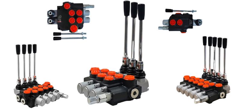
Our offer includes directional control valves designed for use in hydraulic systems of, among others, cranes, lifts, construction, agricultural, and industrial machinery. Their main task is to control the direction of the working fluid flow. Depending on the model, the nominal flow rate ranges from 45 to 170 [l/min] at a maximum working pressure of 350 [bar]. One directional control valve can have a maximum of 8 working sections. In our offer: (monoblocks) with one control lever, two control levers, three control levers, four control levers, five control levers, six control levers, seven control levers.
How to choose a hydraulic directional control valve?
The choice of a hydraulic directional control valve should be adapted to the specific nature of the system and the requirements of the machine in which it will be used. The first step is to determine the type of control the valve should have. Depending on the application, you can choose between manual control (e.g., lever), electric, hydraulic, or electro-hydraulic. Manual directional control valves work well in simple agricultural and construction machines, while electric and electro-hydraulic valves are used in advanced systems requiring remote operation or automation.
Number of valve sections
Another important parameter is the number of sections, i.e., the number of actuators or hydraulic circuits that will be controlled using a single directional control valve. For example, a 2-section valve allows for the operation of two independent actuators – which is an ideal solution for front loaders or forklifts.
Valve flow and maximum pressure
An extremely important factor is the oil flow, expressed in liters per minute (l/min). It must be matched to the efficiency of the hydraulic pump to ensure proper operation of the entire system. Too low a flow can cause a drop in actuator performance, while too high a flow can lead to inefficient operation or component damage. Another issue is the maximum working pressure, which determines what oil pressure the directional control valve can withstand. It should be matched to the parameters of the hydraulic system to avoid overloading and damaging the components. Standard pressure values for directional control valves range from 160 to 250 bar, although in specialized systems they can be much higher.
Valves in directional control valves
It is also worth paying attention to the functions of check and safety valves, which affect the protection of the entire system. For example, relief valves protect the system against excessive pressure increase by diverting excess oil to the tank. Such a solution is particularly important in agricultural and construction machinery, where dynamic pressure changes occur in the system.
Valve connection threads
Finally, make sure that the type of connection threads matches the rest of the hydraulic system. Standard threads used are BSP, NPT, or metric, so it is worth checking the technical specifications of the machines to avoid assembly problems. Example application: In the case of a front loader that handles lifting and tilting the bucket, a 2-section directional control valve with a flow of 40–80 l/min and a pressure of 160–250 bar is most often used. Thanks to this, it is possible to precisely control the movement of the actuators and ensure efficient machine operation.
Types of hydraulic directional control valves:
- 1-section directional control valve
- 2-section directional control valve
- 3-section directional control valve
- 4-section directional control valve
- 5-section directional control valve
- 6-section directional control valve
- electrically controlled directional control valve
Purpose of directional control valves
Directional control valves intended for use in hydraulic systems of cranes, lifts, construction, agricultural, and industrial machinery. They control the direction of the working fluid flow. Controlled by a manual lever or electrically.
Monoblock hydraulic directional control valves
Monoblock directional control valves are the cheapest and most popular ones used on the market - mainly used in machines and devices designed for agriculture. The entire valve is made of a single casting (monoblock), which is then machined. The main supplier of monoblock directional control valves in Europe is BULGARIA.
Sectional directional control valves
Sectional directional control valves are a more expensive and less popular type. Unlike monoblocks, this type of valve consists of individual sections bolted together. It is possible to replace any sections and re-bolt them. Sectional valves are very popular in industrial equipment and forestry equipment.
Hydraulic directional control valves – construction, operation and assembly
A hydraulic directional control valve is one of the key elements of hydraulic systems, responsible for controlling oil flow and the operation of actuators. Depending on the specification, a hydraulic directional control valve consists of various elements, such as the control valve lever, cap, dome, and valves, which together are responsible for its proper operation.
Construction of a hydraulic directional control valve
A hydraulic directional control valve consists of several key elements that together ensure its reliable operation. The valve body constitutes the main housing, containing the hydraulic spool responsible for controlling the oil flow. Depending on the type of control, spool movement can be triggered by a lever, electromagnets, hydraulic, or pneumatic force. Additional components, such as return springs, protective caps, check, and relief valves, increase the durability and safety of the entire system operation. Thanks to their versatility and reliability, hydraulic directional control valves find applications in many fields of industry, from agricultural and construction machinery to industrial hydraulics. The construction of a hydraulic directional control valve is complex and varies depending on the model, however, basic elements such as the lever, valve sections, and valves (e.g., relief valve) are common to most designs. An important part is also the throttle, which regulates the flow of oil.
- Valve body. The basic element of the directional control valve is the body, which acts as a housing and also as a support structure for all internal components. It contains the oil channels and seats for the spool controlling the flow of the working fluid. The body is usually made of durable materials such as cast iron or steel, which guarantees its resistance to high pressures and difficult working conditions.
- Hydraulic spool. Inside the body, there is a spool that is responsible for controlling the direction of oil flow. By moving in different positions, it opens and closes individual oil channels, directing the fluid to the appropriate sections of the hydraulic system. The spool can be moved manually using a lever, electrically using electromagnets, hydraulically, or pneumatically, depending on the type of directional control valve.
- Return springs. To ensure the stability of the spool position and allow it to return to the neutral position after the control is released, return springs are used. They are located on both sides of the spool and are responsible for its automatic setting in the initial position, which protects the system against accidentally leaving the flows open.
- Valve control levers. If the directional control valve is manually controlled, it is equipped with a control lever. It allows the operator to move the spool and thus control the flow of oil in the hydraulic system. In more modern solutions, the lever is replaced by electromagnets, which are activated by an electric signal, allowing the valve to be controlled remotely or automatically.
- Protective caps. To protect sensitive control elements such as the lever or electromagnets, protective caps are used. They are essential, especially in difficult working conditions, where the directional control valve is exposed to contact with dust, moisture, and other external factors that could affect its lifespan.
- Safety valves. Some models of directional control valves have additional safety valves, such as a check valve, which prevents hydraulic oil from flowing back into unwanted channels, and a relief valve, responsible for protecting the system against excessive pressure increase. These are important solutions that ensure the stability of the hydraulic system and protect its components from damage. What is the valve in a hydraulic directional control valve used for? A hydraulic directional control valve may contain various valves performing specific functions: Relief valve – protects the system against excessive pressure increase by directing excess oil to the tank. Check valve – blocks oil backflow and protects against uncontrolled movement of the actuator. Throttle valve – regulates oil flow, affecting the speed of the actuator movement. Solenoid valve – enables flow control using electrical pulses. In practice, the valves built into the directional control valve are responsible for the safety and control of the hydraulic system operation.
- Connection ports. There are also connection ports on the valve housing, i.e., ports through which the hydraulic oil flows. Among them, one can distinguish the pressure port, where oil is supplied from the pump, working ports, directing oil to actuators or hydraulic motors, and the return port, through which the oil returns to the tank after completing the work.
- Valve seals. To ensure the entire system is leak-proof and operates without pressure losses, various types of seals are included in the construction of the directional control valve. They are usually made of rubber resistant to hydraulic oil and high temperatures, which guarantees long-lasting and failure-free operation.
Operating principle of a hydraulic directional control valve
A hydraulic directional control valve is one of the basic components of power hydraulic systems, whose main task is to control the direction of hydraulic oil flow. It works on the principle of controlling the flow of working fluid in the system, which allows for precise starting and stopping of actuators, hydraulic motors, and other execution elements. A hydraulic directional control valve works on the principle of regulating oil flow in the hydraulic system, which allows for controlling actuators and other execution elements. Control is carried out using a lever or handle of the valve, which is responsible for changing the position of internal valves, which in effect directs oil to the appropriate sections. Power to the hydraulic directional control valve is provided by a hydraulic pump, and excess pressure is regulated by a relief valve.
How does a hydraulic directional control valve work?
A hydraulic directional control valve consists of a body containing a spool controlling the oil flow. Depending on its design, it can have a different number of sections, which allows for the simultaneous control of many hydraulic receivers. Basic stages of valve operation: 1) Supply of pressure to the system – hydraulic oil is pumped by the pump and supplied to the inlet of the directional control valve. 2.) Control of oil movement – moving the spool to the appropriate position opens the flow channels, which allows directing the working fluid to a specific section of the hydraulic system. 3.) Transfer of energy to the receiver – under the influence of the oil flow, the actuator or hydraulic motor performs the intended movement (e.g., extension of the actuator rod, rotation of the hydraulic motor shaft). 4.) Stopping or changing the direction of flow – returning the spool to the neutral position cuts off the oil supply or redirects it to another section of the system, enabling a change in the actuator movement or stopping its operation.
Types of control for hydraulic directional control valves
Hydraulic directional control valves can be controlled in several ways, depending on the system requirements and application:
- Manual control – operated by a lever or knob, used in simple hydraulic systems, e.g., in agricultural loaders.
- Electric control – uses electromagnets to move the spool, enabling automatic control of machines, e.g., in construction vehicles.
- Hydraulic control – uses oil pressure to control the spool, used in more complex systems.
- Pneumatic control – uses compressed air to move the spool, often found in systems where a combination of hydraulics and pneumatics is required.
Why is a hydraulic directional control valve necessary? Hydraulic directional control valves are a basic element of hydraulic systems because they allow for: ✔️ precise control of the operation of actuators and hydraulic motors, ✔️ changing the direction of movement of the machine's working elements ✔️ ensuring smooth and effective operation of the hydraulic system ✔️ protecting the system against overload and uncontrolled oil flow. Thanks to their functionality, directional control valves find wide application in mobile hydraulics (agricultural, construction, forestry machinery) and in industry, where precise control of actuators and other execution elements is required.
Markings on the directional control valve
Hydraulic directional control valves have various markings that help in their identification and proper connection to the system. The marking of a hydraulic directional control valve determines its functions, flow capacity, and type of valves, which is particularly important during installation. Important to remember: P = supply ; T = return ; N = output for serial connection of the directional control valve using a pressure carry-over sleeve
What does "C" mean on a hydraulic directional control valve?
The letter "C" on a hydraulic directional control valve most often means the pressure port of an additional hydraulic circuit or a connection for external control. Depending on the manufacturer and the specific model, it can be: 1) Supply port of an auxiliary section – e.g., for an additional actuator or control circuit. 2) Connection for external hydraulic control – used in electro-hydraulic directional control valves. 3) Pilot pressure connection – in systems requiring pilot control. To be sure what "C" means in a given model, it is worth checking the technical documentation of the directional control valve.
What does "T" mean on the directional control valve?
The letter "T" on a hydraulic directional control valve means the outlet port ("Tank"), i.e., the place through which hydraulic oil returns to the tank after completing work. It is a key element of the closed circuit in the hydraulic system. Application of the "T" port in the valve: 1) Drainage of excess oil after work. 2) Connection to an oil filter to remove contaminants before the oil returns to the tank. 3) Pressure stabilization in the system through the relief valve. In electro-hydraulic valves, there may be several outlet ports T1, T2 – for different return circuits.
Where is the supply located in a hydraulic directional control valve?
In most standard hydraulic directional control valves: Supply (P – "Pressure") is located on the valve body, usually on one of the main side ports. The outlet (T – "Tank") leads the oil back to the hydraulic tank. Working ports (A and B) direct the oil to actuators or hydraulic motors. In multi-section systems, supply can be realized through a serial inlet or supply to intermediate sections.
Hydraulic directional control valve assembly and connection
Correct assembly of a hydraulic directional control valve is key to its reliable operation. It requires proper connection to the system, according to the hydraulic directional control valve diagram and the technical cross-section. An important stage of assembly is the connection of valves and directional control valve sections to ensure proper oil flow.
Seals and threaded connections
Assembly of a hydraulic directional control valve always requires the use of appropriate seals. Depending on the type of connections, these can be cone seals, flat seals, O-rings, or sealing tape. Only seals compatible with hydraulic oil and the working pressure range should be used. Threaded connections should be tightened with care. Tightening too loosely will cause leaks, while tightening too much can lead to damage to the valve body.
Spare parts and repair kits for directional control valves
During operation, hydraulic directional control valves may require repairs, so it is important to have access to directional control valve spare parts and hydraulic valve repair kits. Repairs include replacing worn elements such as seals, levers (control handle), or valves, which allows for extending the device's lifespan.
Hydraulic section
What is a hydraulic section? A hydraulic section is an element of a hydraulic directional control valve that controls the oil flow to a specific circuit. It can be part of a monoblock or modular directional control valve, and its task is to control the pressure, direction, and intensity of oil flow. A hydraulic section is one of the key construction units in hydraulic directional control valves, responsible for controlling the flow of hydraulic oil in the system. Each section performs a specific function – it can control one hydraulic circuit or work in a team with other sections, creating a modular valve adapted to various applications. What functions does a hydraulic section perform? Where are hydraulic sections used? Hydraulic sections are commonly used in: construction machinery (e.g., excavators, loaders), agricultural machinery (e.g., tractors, combines), industrial systems (e.g., hydraulic presses, transport systems). Hydraulic sections enable: oil flow control – they regulate the direction and intensity of the working fluid flow, powering actuators and hydraulic motors – each section serves a specific receiver (e.g., actuator or hydraulic motor), pressure control – they are often equipped with safety valves that protect the system against excessive pressure increase. connection into a modular system – in multi-section systems, each section controls a separate hydraulic circuit, which allows for independent control of several receivers.
Types of hydraulic sections
Depending on the type of directional control valve, you can find different types of sections: ✔️ Monoblock sections – used in one-piece directional control valves, where all sections are cast as a single block. ✔️ Modular sections (multi-section) – enable the configuration of the system depending on the number of sections needed and their functions.
BADESTNOST - manufacturer of directional control valves
Badestnost is a Bulgarian company specializing in the production of hydraulic directional control valves and components since 1902. Its products find applications in areas such as agriculture, automotive, and broadly understood mechanical engineering, wherever control of the direction of working fluid flow between pressure generators and receivers is required. Over 80% of the company's production is exported to markets on all continents, including Europe, both Americas, the Middle East, Australia, and New Zealand. The company's offer includes, among others, monoblock directional control valves, electromagnetically controlled, available in various configurations, which allows for adapting them to specific application needs and hydraulic diagrams. Badestnost is a renowned manufacturer of high-quality hydraulic directional control valves. Products of this brand are characterized by solid construction, reliability, and wide application in various industry sectors. BADENOST directional control valves are characterized by High quality of workmanship: Badestnost monoblock directional control valves are characterized by a compact design, stable operation, and high versatility, which allows for their use in various machines and devices powered hydraulically. The valves are used in agricultural, forestry, construction, and industrial machines, such as front loaders, forestry trailers, or forklifts. The offer includes one-, two-, and three-section directional control valves with flows of 40 l/min, 80 l/min, and 120 l/min, which allows for matching the appropriate model to the specific needs of the user.
1-section hydraulic directional control valve
A 1-section hydraulic directional control valve is a compact device used in power hydraulic systems to control one hydraulic circuit. It enables precise management of oil flow to a single-acting or double-acting actuator. It is used, among others, in hydraulic lifts, where it regulates the lifting and lowering of the load, as well as in hydraulic presses, enabling controlled material compression.
2-section hydraulic directional control valve
A 2-section hydraulic directional control valve allows for controlling two independent actuators or hydraulic motors. It is used in machines where managing several circuits simultaneously is required. Often used in front loaders for controlling lifting and bucket tilt, forklifts for controlling fork lifting height, as well as in forestry machines for operating grippers.
3-section directional control valve
A 3-section hydraulic directional control valve enables the operation of three independent hydraulic circuits, which allows for even more comprehensive control over machines. It finds application in excavators, where it controls boom, arm, and bucket movements, as well as in forestry trailers with a hydraulic crane for operating the gripper and boom rotation.
4-section hydraulic directional control valve
A 4-section hydraulic directional control valve is an expanded version of a standard valve, allowing for the control of four actuators or other hydraulic receivers. It is widely used in fertilizer spreaders for regulating sowing, hydraulic cranes for controlling lifting, arm extension, and rotation, as well as in municipal machines for operating multifunctional tools.
Hydraulic directional control valve cap
A hydraulic directional control valve cap is a protective cover mounted on the valve, protecting its internal components from dirt and mechanical damage. It finds application in agricultural, construction, and forestry machinery, where it protects control elements from dust, water, and other contaminants, extending the life of the devices.
Electro-hydraulic directional control valve
An electro-hydraulic directional control valve is a modern electrically controlled device that regulates oil flow in hydraulic systems without the need for manual action. It is used in modern agricultural tractors for automatic control of hydraulic functions, in industrial control systems for precise regulation of actuators, and in military vehicles for suspension operation and stabilization.
Electric hydraulic directional control valve
An electric hydraulic directional control valve is a version of a valve in which the control of the oil flow direction is carried out using electric control valves. It finds application in industrial automation, robotics, and hydraulic control systems in specialized vehicles. It enables precise control over the movement of actuators, increasing efficiency and work safety.
Hydraulic directional control valve lever
A hydraulic directional control valve lever is a mechanically controlled element that enables the operation of a hydraulic directional control valve and regulation of the oil flow direction. It is used in excavators, bulldozers, and hydraulic cranes, where it allows the operator to smoothly control the movement of the actuators, increasing the precision of the machine's work.
3-section cable directional control valve
A 3-section cable directional control valve is a hydraulic control valve that enables the operation of three independent hydraulic circuits using control cables. It is used in forestry machines for controlling hydraulic cranes, in snowplows for regulating the tilt angle, and in municipal machines for controlling equipment. Thanks to the use of control cables, it allows for convenient operation of the directional control valve at a distance, increasing comfort of use.
Examples of valve applications: Ursus C360 and Bizon
Hydraulic directional control valves are widely used in agricultural machinery such as Ursus C360 or Bizon. In the case of Ursus C360, the hydraulic directional control valve controls the operation of the hydraulic lift system. In Bizon-type machines, it is responsible for controlling the working mechanisms, which requires special precision and durability of the directional control valve.
Monoblock directional control valve
A monoblock directional control valve is a key element of every power hydraulic system. It is responsible for controlling the direction of hydraulic oil flow, and thus – for the movement of actuators, hydraulic motors, or other power receivers. Thanks to its compact design and high durability, monoblock valves are commonly used in agricultural, industrial, forestry, construction, and transport machinery. The Hydron offer includes professional hydraulic monoblock directional control valves that combine high quality of workmanship with reliability and control precision.
What is a monoblock hydraulic directional control valve?
A monoblock directional control valve is a hydraulic valve in which all oil channels and control elements are integrated in one block (monolith). Unlike sectional valves, which consist of several connected sections, the monoblock version has a fixed number of sections and a compact structure. Such a construction ensures: lower risk of leaks (fewer connections and seals), greater resistance to vibrations and overloads, compact dimensions – ideal for mobile machines, easy assembly and operation. In practice, a monoblock directional control valve acts as a "control center" for the hydraulic system – it directs the flow of oil to the appropriate actuators depending on the position of the lever or the type of control.
Construction of a monoblock directional control valve
A monoblock directional control valve is built from a single body, containing: oil channels – supplying and discharging oil from the pump and to the tank, control spools (reels) – moving in seats and directing the oil flow, centering springs – keeping the spool in the neutral position, safety and check valves – protecting the system against overpressure, control levers or remote control mechanisms (cables, joysticks, actuators). Depending on the version, the valve can have one, two, or three working sections, which enables the control of an appropriate number of hydraulic actuators. Additionally, variants with different types of control are available – manual, hydraulic, or electric.
Application of monoblock directional control valves
Monoblock directional control valves find applications in various machines and devices where precise oil flow control is required. Most often they are used in: agricultural machinery (tractors, front loaders, trailers, spreaders), construction machinery (excavators, mini-loaders, lifts), forestry and municipal machinery (cranes, winches, sweepers), industrial systems (hydraulic tables, presses, test equipment), mobile systems where compact dimensions and reliability of operation are key. Depending on the needs, monoblock valves can be equipped with additional functions, such as: adjustable relief valve, floating position (float), possibility of connecting tandem sections or additional controls.
Advantages of using monoblock directional control valves
A monoblock directional control valve is a solution valued by both designers and machine users. Its main advantages are: compact construction and small dimensions, simple installation and service, resistance to damage and vibrations, low weight and high durability, precise flow control, availability of many configurations and working flows, possibility of working with different types of hydraulic oils. Thanks to this, monoblock directional control valves are an excellent choice in situations where simplicity, reliability, and durability count.
Monoblock vs sectional directional control valve – differences
It is worth mentioning the differences between a monoblock and a sectionaldirectional control valve, as both designs are often used in power hydraulics.
| Feature | Monoblock directional control valve | Sectional directional control valve |
|---|---|---|
| Construction | Uniform body (block) | Modular, from sections connected by bolts |
| Number of sections | Fixed (1–3) | Any, easy expansion |
| Tightness | Very high | Requires more seals |
| Dimensions | Compact | Larger |
| Service | Simpler, fewer parts | Easier expansion |
| Application | Mobile, agricultural machines | Industry, hydraulic lines with many circuits |
In short: monoblock directional control valve is an ideal choice when you need a simple and durable solution with small dimensions, and sectional – when the system requires many independent circuits.
Connecting two hydraulic directional control valves — the role of the pressure carry-over sleeve
In a situation where there is a need to expand the hydraulic system — for example, adding another section or a second directional control valve — a correct connection between them becomes necessary. For this purpose, special fittings called pressure carry-over sleeves are used. A pressure carry-over sleeve allows for: transfer of pressure from the first directional control valve to the next in a serial line, maintaining continuity of oil flow without the need for additional lines between directional control valves, protection against "backflow" pressure effects — i.e., a situation in which oil from the second valve could flow back to the first. In practice, the valve design often includes a port marked as "N" or "neutral / bypass", which is factory-plugged. It is in this place that the plug is removed and a pressure carry-over sleeveis mounted, through which the supply (pressure) flows further to the second unit. Important aspects to consider: The sleeve should have threads and cross-sections consistent with port "N" of the directional control valve (most commonly used diameters, depending on the valve design). Working pressure in the system must be adjusted – the sleeve must withstand the same or higher pressure than the rest of the installation. After connecting both directional control valves through the sleeve, both units must have returns (T ports) directed to the oil tank to avoid the formation of overpressure or lateral flow. Thanks to the use of a pressure carry-over sleeve, it is possible to flexibly expand the hydraulic installation without significant structural interference. It is a proven solution that ensures tightness, system continuity, and problem-free oil flow control.
Hydraulic directional control valve connection diagram
A hydraulic directional control valve connection diagram is a basic element of the technical documentation of every power hydraulic system. It allows for understanding the manner of hydraulic oil flow between the pump, directional control valve, actuator, and tank. Correct connection of the directional control valve determines whether the system will work effectively, without leaks and pressure losses. A hydraulic directional control valve performs the function of controlling the direction of oil flow – depending on the position of the lever or solenoid valve, it directs the oil to the appropriate port of the actuator (A or B), enabling its extension or retraction.
Hydraulic directional control valve connection - basic diagram of connecting a hydraulic directional control valve:
- Port P – supply (Pressure)
A line from the hydraulic pumpis connected to this port, which pumps oil under pressure to the directional control valve. The pump should be protected by a relief valve to protect the system against overpressure. -
Port T – return (Tank)
From port T, the oil returns to the hydraulic tank after completing the work in the system. Care should be taken that the return line is sufficiently wide, which avoids excessive flow resistance and oil overheating. -
Ports A and B – working outputs (Actuator ports)
These are the lines leading to the hydraulic actuator or other receiver. When the valve lever directs flow to port A, oil goes to one side of the actuator, causing the piston rod to extend. When the flow is directed to port B, the actuator retracts the piston rod, and oil from the second chamber returns through the directional control valve to the tank. -
Port N or PB – pressure carry-over (Power Beyond)
In the case of multi-section directional control valves or those connected in series, this port serves to pass pressure further to the next directional control valve. If it is not used, it should be properly plugged or a pressure carry-over sleeve should be used. -
Auxiliary valves
Depending on the type of installation, additional elements may be mounted at the directional control valve, such as: check valve – prevents oil from flowing back, relief valve – limits the maximum pressure in the system, return filter – protects components against contaminants.
What does the valve flow look like in practice?
During operation, the pump pushes oil to the Pport, and the directional control valve — depending on the setting — directs the flow to A or B. Oil from the other side of the actuator goes through the return port to T, and then to the tank. After releasing the lever, the valve goes into a neutral position, in which the flow can be completely blocked or directed directly from P to T (depending on the type of directional control valve).
Typical system with a single-section directional control valve
In simple hydraulic systems, 1-sectiondirectional control valves are used, which serve one actuator. The pump feeds the directional control valve, from which two working lines lead – to the actuator (A, B) – and one return to the tank (T). In multi-section systems (e.g., in construction machines), subsequent valves are connected through the Power Beyond (N)port, which allows for powering several receivers from one pump.
Hydraulic distributing valve
Hydraulic distributing valves are elements of the power hydraulic system used to control the direction of hydraulic oil flow. It enables control over the movement of actuators or hydraulic motors – deciding which way the piston is to move or the motor rotate. Thanks to distributing valves, precise control over the operation of machines such as tractors, excavators, or hydraulic presses is possible. The term distributing valves most often refers precisely to hydraulic directional control valves.
Catalogs to download:
Check also:
Photo gallery


expand text Single-section plunger directional control valve expand text Single-section directional control valve with floating section
Single-section directional control valve with floating section
A single-section directional control valve with a floating section is a power hydraulics element that controls the flow of hydraulic oil in the system. A single-section valve has only one working section, which means it controls one hydraulic circuit – e.g., one actuator or one hydraulic motor.
Floating section
A floating section (the so-called "float" position) is an additional function in the valve lever that allows the receiver – most often an actuator – to move freely without forcing the oil flow. In this position, both working lines of the actuator are connected to the return to the tank, so the piston rod can move freely, following the ground or load, without resistance.
Application of the floating section
The floating section finds application in agricultural and construction machines such as front loaders, plows, or graders. It allows the attachment – e.g., bucket, blade, or plow – to independently "copy" the terrain without the need for constant manual control. This solution reduces working resistance and component wear because the actuator does not block the movement of the attachment.
expand text What is an oil directional control valve?
What is an oil directional control valve?
An oil directional control valve is one of the key elements in power hydraulics systems. Its primary function is to control the flow of hydraulic oil in the installation – i.e., directing it to the appropriate receivers, such as actuators or hydraulic motors. Thanks to this, it is possible to perform specific movements, e.g., lifting, lowering, extending, or rotating machine parts.
How does an oil directional control valve work?
An oil directional control valve works by changing the position of the spool (or other control element) that opens and closes individual flow channels. Depending on the valve design, oil can be directed to different parts of the hydraulic system, which allows for precise control of the machine's operation.
Types of oil directional control valves
Monoblock valves – tight, compact, used in simpler systems.
Sectional valves – modular, allow for expanding the system and handling many functions simultaneously.
Valves controlled manually, electrically, or hydraulically – differ in the way the oil flow is controlled.
Application of oil directional control valves
Oil directional control valves are used in:
• construction machinery (excavators, loaders),
• agricultural machinery (tractors, presses, sprayers),
• industrial and production lines,
• forklifts, lifting devices, and other mobile machines.
The oil directional control valve thus serves as the "control center" of the entire hydraulic system, ensuring effective and safe operation of the devices.
expand text Sectional directional control valve
Sectional directional control valve
A sectional directional control valve is an extremely important element of every power hydraulics system. Its task is to precisely control the direction of hydraulic oil flow and thus control the operation of actuators and hydraulic motors. Thanks to it, it is possible to perform many operations simultaneously – lifting, lowering, rotation, or movement in different axes. The Hydron offer includes modern hydraulic directional control valves of various designs that can be perfectly adapted to the needs of any machine.
Types of hydraulic directional control valves
Hydraulic directional control valves are primarily divided into two construction types – monoblock and sectional. Both solutions perform the same function but differ in construction, expansion possibilities, and servicing methods.
Monoblock directional control valves
The monoblock version is a design in which the entire valve body constitutes a single casting. Such a solution ensures exceptional tightness, resistance to damage, and compact dimensions. Monoblock directional control valves are particularly valued in simple hydraulic systems – e.g., in agricultural, municipal, or industrial machines, where the system does not require frequent configuration changes. Their advantage is high reliability and long operating time even in difficult working conditions.
Sectional directional control valves
Sectional directional control valves (also called modular) are solutions created for more expanded systems. Each valve consists of separate sections – and each section controls an independent hydraulic circuit. Such a construction allows for free configuration modification – you can easily add or replace a section without having to dismantle the entire device. Thanks to this, sectional valves are extremely practical in multifunctional machines such as telescopic loaders, cranes, derricks, or forestry vehicles.
How many sections can a directional control valve have?
The number of sections depends on the requirements of a specific hydraulic system. In practice, valves ranging from single-section to eight-section, and even larger configurations in specialized industrial machines, are used.
Single-section directional control valve – to serve one actuator or one working function.
Two- and three-section directional control valve – used in machines having several independent circuits, e.g., in loaders.
Multi-section directional control valve – used in expanded systems where simultaneous control of several functions is necessary, e.g., in agricultural machinery, hydraulic cranes, or technological lines.
The Hydron offer includes directional control valves with various flow rates and configurations – from compact versions up to 45 l/min to large industrial models with flows up to 170 l/min and maximum working pressure reaching 350 bar.
Application of sectional directional control valves
Sectional directional control valves are essential in systems where the operation of several functions at once is required. Depending on the type of machine, they can control various actuators, hydraulic motors, or working tools. They find application in, among others:
- construction machinery (excavators, loaders, lifts),
- agricultural machinery (presses, spreaders, combines),
- municipal vehicles (garbage trucks, plows, bucket lifts),
- industrial equipment and stationary hydraulic units.
Their modular design allows for flexible adjustment of the number of sections to the current needs of the user, as well as fast service in case of failure of one of them.
Advantages of directional control valves available at Hydron
The directional control valves offered by Hydron are characterized by solid workmanship, high precision of work, and reliability. They stand out for:
- resistance to high pressures and long-term loads,
- the possibility of easy servicing and section replacement,
- smooth regulation of oil flow,
- adaptation to various hydraulic systems,
- availability of versions with different types of control (manual, electric, pneumatic).
Each product has appropriate quality certificates, which guarantees compliance with European safety standards. Hydron, thanks to many years of experience and constant presence in the power hydraulics industry, provides solutions that are proven in practice and valued by professionals.
Professional advice and fast execution
The Hydron team provides comprehensive help in choosing the right directional control valve – from demand analysis to implementation in the hydraulic system. High inventory levels and efficient logistics guarantee instant order fulfillment. Thanks to this, customers gain not only reliable products but also full technical support.
Order now and improve your work
We encourage you to visit the site sklep.hydron.com.pl, where you will find a wide offer of monoblock and sectional directional control valves with various parameters. Contact our team of advisors, and we will help you choose a solution perfectly tailored to your needs.