








back to : technical information on power hydraulics
Hydraulic symbols - diagrams
Graphic symbols of power hydraulics
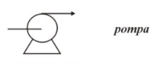
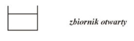
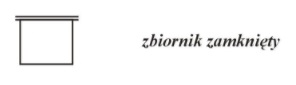
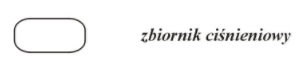
The diagram presents basic graphic symbols used in hydraulic diagrams. Markings of lines, various types of valves, tanks, pumps, motor and pressure gauge. Graphic symbols placed on this page were developed based on the current PN/ISO-1219-1 standard. Power hydraulics symbols are the key to understanding the principles of operation and construction of hydraulic systems. Thanks to them, it is possible to uniquely represent the structure of the system, its elements, and the direction of fluid flow. Every specialist in this field should know the basic symbols to efficiently read and create diagrams, which translates into safe and effective management of hydraulic systems. Knowledge of hydraulic symbols is the foundation of effective work with hydraulic systems and one of the most important aspects in practical power hydraulics.































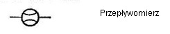

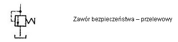
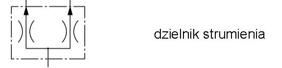



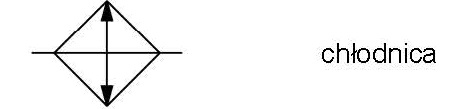
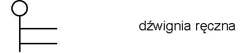
Power hydraulics symbols: basic markings and their meaning
Power hydraulics is an advanced field of technology in which control systems for liquid under pressure play a key role. To facilitate the design and reading of diagrams, graphic hydraulic symbols are used, which represent individual components in a standardized way. Knowledge of these symbols is essential for every specialist involved in power hydraulics, from designers to service technicians. Below we present the most important power hydraulics symbols and their functions.
Why are power hydraulics symbols so important ?
Hydraulic symbols enable the presentation of complex systems in a clear and unambiguous way, which facilitates the design, analysis, and repair of hydraulic systems. Their standardization (ISO 1219-1 standards) allows for the understanding of diagrams worldwide, regardless of the language or specific application. Proper recognition of symbols in power hydraulics is crucial for safe and effective work with hydraulic systems.
Basic Symbols in Power Hydraulics
-
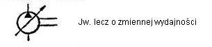
Hydraulic Pumps - Symbols for hydraulic pumps differ depending on the type of pump (e.g., gear pump, vane pump, piston pump). Most often they are indicated by a triangle in a circle, pointing in the direction of liquid flow. For example: Gear pump: Triangle pointing right inside the circle. Vane pump: Triangle pointing right with additional lines.
-
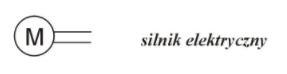
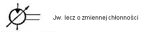
Hydraulic Motors - A hydraulic motor is similar to a pump, but the symbol indicates the opposite direction of flow. The triangle symbol points in the opposite direction, signifying liquid flow generating movement.
-
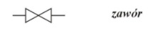
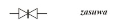
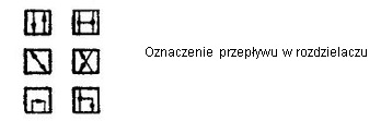
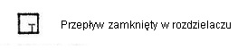
Directional Control Valves - Directional control valves are some of the most common symbols in power hydraulics; they are responsible for controlling the direction of liquid flow. Basic types of valves include: 2/2 Valve – Two ports, two positions, marked as a rectangle with two arrows indicating the direction of flow. 3/2 Valve – Three ports, two positions, used to control cylinders and actuators. 4/2 and 5/2 Valve – With more complex symbols, often used to control more complicated systems.
-
Pressure Reducing and Safety Valves - These valves are used to control pressure in the system and prevent it from being exceeded. The symbol for a pressure reducing valve often includes a spring and a dashed line, which symbolizes the pressure setting in the system.
-
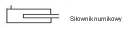
Hydraulic Cylinders - Cylinders are actuators that convert liquid energy into linear or rotary motion. The symbol for a linear cylinder is a rectangle with a line passing through the center, representing piston movement. In double-acting cylinders, arrows symbolizing movement directions are added.
-
Lines and Flow Lines Lines representing the flow of liquid in the system also have their specific designations: Pressure line – Solid line, which indicates flow under pressure. Drain line – Dashed line, symbolizing liquid drainage. Return line – Sometimes marked as a double solid line.
-
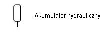
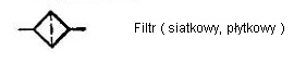
Filters and Accumulators - Filters, which are responsible for liquid cleanliness, are marked as a circle with an internal dashed line or grid. Hydraulic accumulators, which store liquid energy under pressure, are often marked as a circle with an internal "X" or an arrow.
Other symbols used in power hydraulics
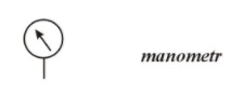
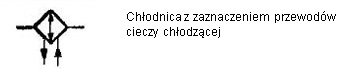
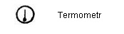
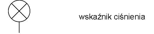
In addition to the main components, there are many symbols in power hydraulics for more advanced elements, such as: Heat exchangers – Symbolized by a rectangle with internal horizontal or vertical lines. Pressure gauges – Used for pressure measurement, marked as a circle with the letter „P” inside. Check valves and throttles – One-way valves often have an arrow symbol pointing in one direction, indicating liquid flow in only one direction, while throttles regulate the flow and are marked by diagonal lines in the lines.
How to recognize and use symbols on a diagram ?
The ability to read hydraulic symbols is essential for designing, installing, and maintaining hydraulic systems. Understanding individual symbols allows for quick identification of functions and locations of elements in the system and enables the diagnosis of potential problems. In the case of complex hydraulic installations, correct interpretation of diagrams significantly speeds up repairs and servicing.
Standards for graphic symbols in power hydraulics
Hydraulic symbols are standardized according to ISO 1219-1 and ISO 5599, which ensures their uniformity worldwide. Thanks to these standards, it is possible to seamlessly read diagrams even in foreign countries, which is of key importance for companies operating globally and engineers working in different markets.